
3D Prints Splitting Between Layers? Causes & Fixes for Weak Layer Adhesion
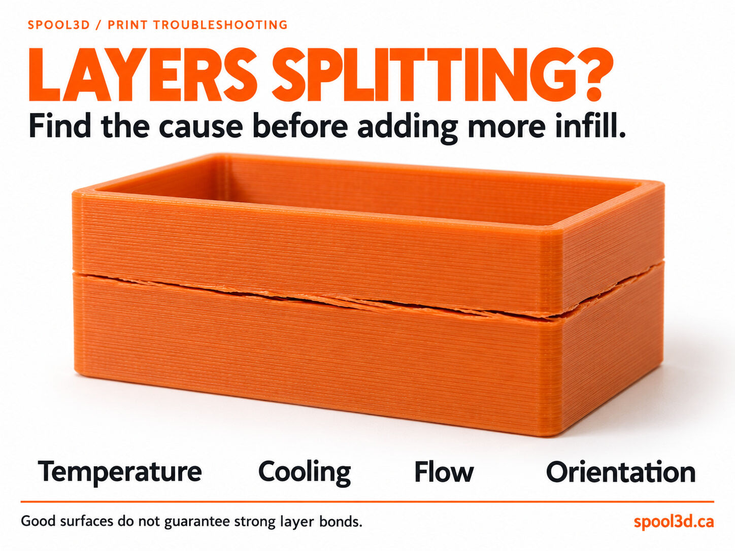
A 3D print can have a smooth surface, tidy corners and a clean top layer, then split the first time you tighten a screw or put it to use.
Sometimes the failure happens before the print even finishes. A horizontal crack opens in a tall wall, and the printer keeps adding material above it. In other cases, the part stays intact on the build plate but breaks along a layer line when you bend or load it.
Both situations deserve a closer look at layer adhesion: how well each new layer bonds to the one below it. Temperature, cooling, extrusion rate, filament condition and the way the part is oriented can all matter. Adding more infill is not automatically the fix.
1. Work out what actually failed
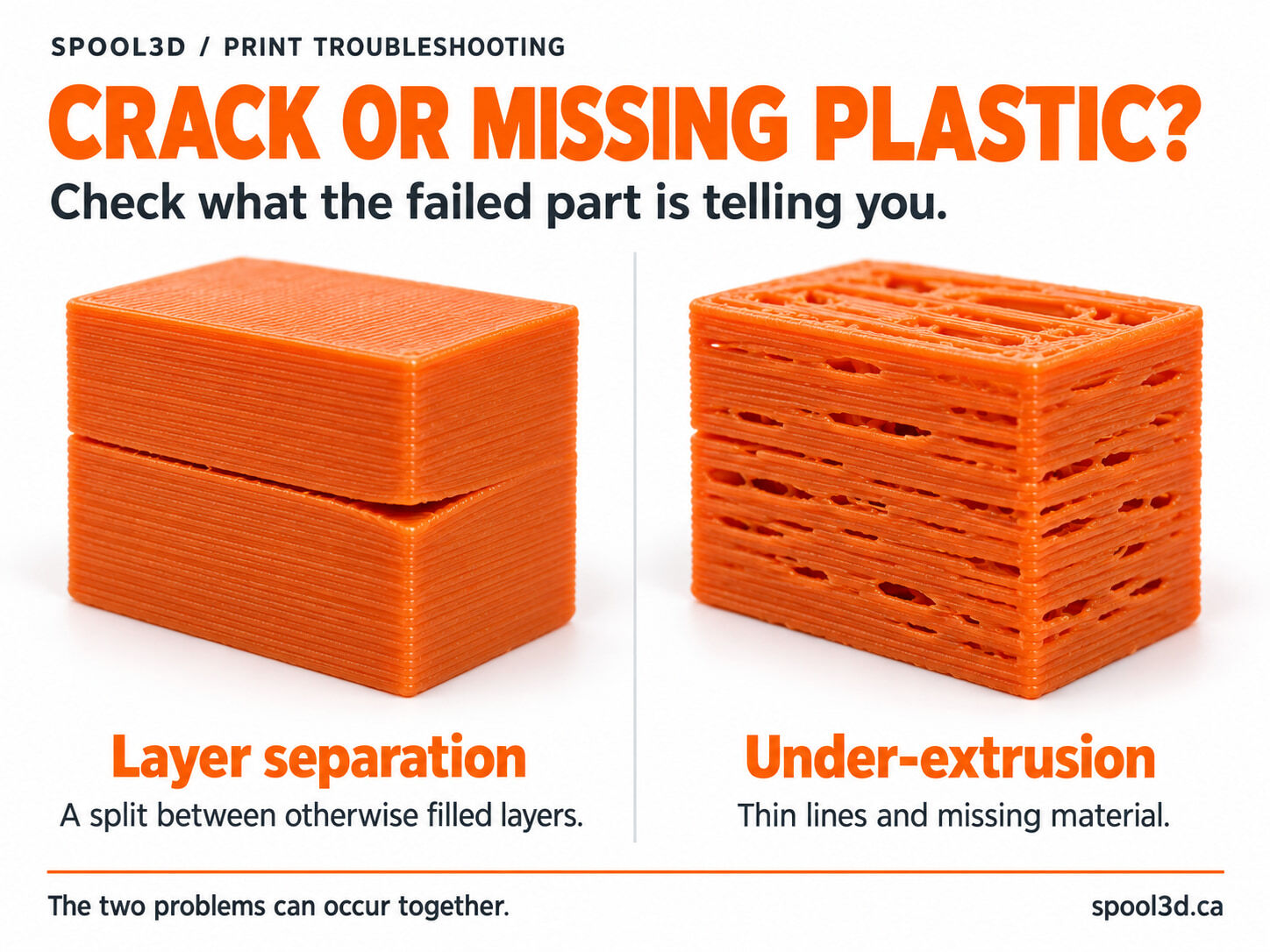
Look at the failed area before changing settings. Several different problems can leave a horizontal defect:
- Layer separation: a crack opens between layers. The edges may lift or curl slightly while the surrounding walls remain dense.
- Under-extrusion: thin lines or missing material leave gaps and weak areas.
- A layer shift: the upper portion moves sideways relative to the lower portion.
- A design or loading problem: the part breaks at a thin section, sharp corner or fastener, even though extrusion looks consistent.
These problems can overlap. Under-extrusion reduces the material available to form a bond, so a poorly filled section may also split between layers.
If the walls are full of gaps, start with our 3D printer under-extrusion troubleshooting guide. A temperature or cooling adjustment cannot make up for a nozzle that is not delivering enough plastic.
2. Check temperature against the material and print speed
The nozzle temperature needs to suit both the filament and the rate at which it is being extruded. A setting that produces a decent-looking slow print may give poor results when the same material is pushed much faster.
Start by confirming the selected filament profile. An incorrect preset is easier to fix than an entire collection of compensating adjustments.
If the material is being printed near the low end of its recommended range, test a small increase, such as 5°C, while keeping the other settings unchanged. Stay within the filament manufacturer's recommendations and the hotend's limits.
Compare the fully cooled parts, not just their surface finish. A shinier surface is not a strength measurement. If a reasonable temperature adjustment does not help, move on to flow and cooling instead of continuing to turn up the heat.
3. Check how much plastic the hotend is being asked to melt
High movement speed does not guarantee that the hotend can melt enough filament for every combination of line width and layer height.
If weakness appears after switching to a faster preset, increasing layer height or fitting a larger nozzle, check the maximum volumetric speed in the filament profile. This limits the volume of material requested per second.
As a diagnostic test, reduce the requested flow and print the same part again. Improvement tells you that extrusion demand is involved; it does not identify the cause by itself. The original demand may have been too high, or a partial clog, low temperature or feeding fault may have reduced the hotend's practical capacity.
If you also hear clicking or find ground filament, inspect the feed system. Our guide to extruder clicking and skipping covers that side of the diagnosis.
4. Adjust part cooling for the material
Part cooling helps fresh extrusion hold its shape, especially on bridges, overhangs and small features. Excessive cooling can also make layer bonding worse or encourage shrinkage-related cracking. The useful balance depends on the material and geometry.
| Material | What to check | What to avoid |
|---|---|---|
| PLA | Start from the filament profile; retain enough cooling for small details and overhangs. | Turning every fan off as a general strength fix. |
| PETG | Test whether less part cooling improves bonding while preserving the required shape. | Choosing fan speed only by how clean a bridge looks. |
| ABS / ASA | Review drafts, enclosure conditions and the material's low-cooling profile. | Using aggressive PLA-style cooling across the whole part. |
Check ordinary wall cooling, bridge or overhang overrides, and any auxiliary fan separately. A high fan setting may apply only to certain features.
Part cooling and heatsink cooling are different jobs. Do not disable the hotend's heatsink fan to improve layer adhesion. That fan keeps the cold side of the hotend cool; interfering with it can cause heat creep and jams.
5. Look for drafts and uneven enclosure conditions
A large ABS or ASA print can develop a crack while it cools unevenly. A room draft, a strong fan blowing on one side or opening the enclosure during printing may change the conditions around the part.
A heated bed helps near the base, but it does not keep the full height of a tall print at the same temperature. Use an enclosure and chamber settings appropriate for the material and printer, and let the finished part cool according to the manufacturer's guidance before removing it.
Do not apply the same enclosure strategy to every filament. Keeping PLA in an excessively warm chamber can create a different problem, as we explain in our heat-creep guide.
If the base is lifting as well, read 3D Print Warping After a Good First Layer? Shrinkage can stress both the bed connection and the bonds higher up the part.
6. Confirm that layer height and line width suit the nozzle
If you recently changed nozzles or built a custom fast profile, check the installed nozzle diameter against the slicer preset. Layer height and extrusion width should be within the range supported by that nozzle and profile.
Very tall layers or unusual line-width settings can change the way adjacent layers contact each other and increase the flow demand. Return to a known-good profile before trying to fix the result with a large flow-ratio adjustment.
Use a moderate layer height as your comparison. The smallest available layer height is not automatically the strongest choice, and extra extrusion is not a substitute for a correctly matched profile.
7. Consider how the part is loaded
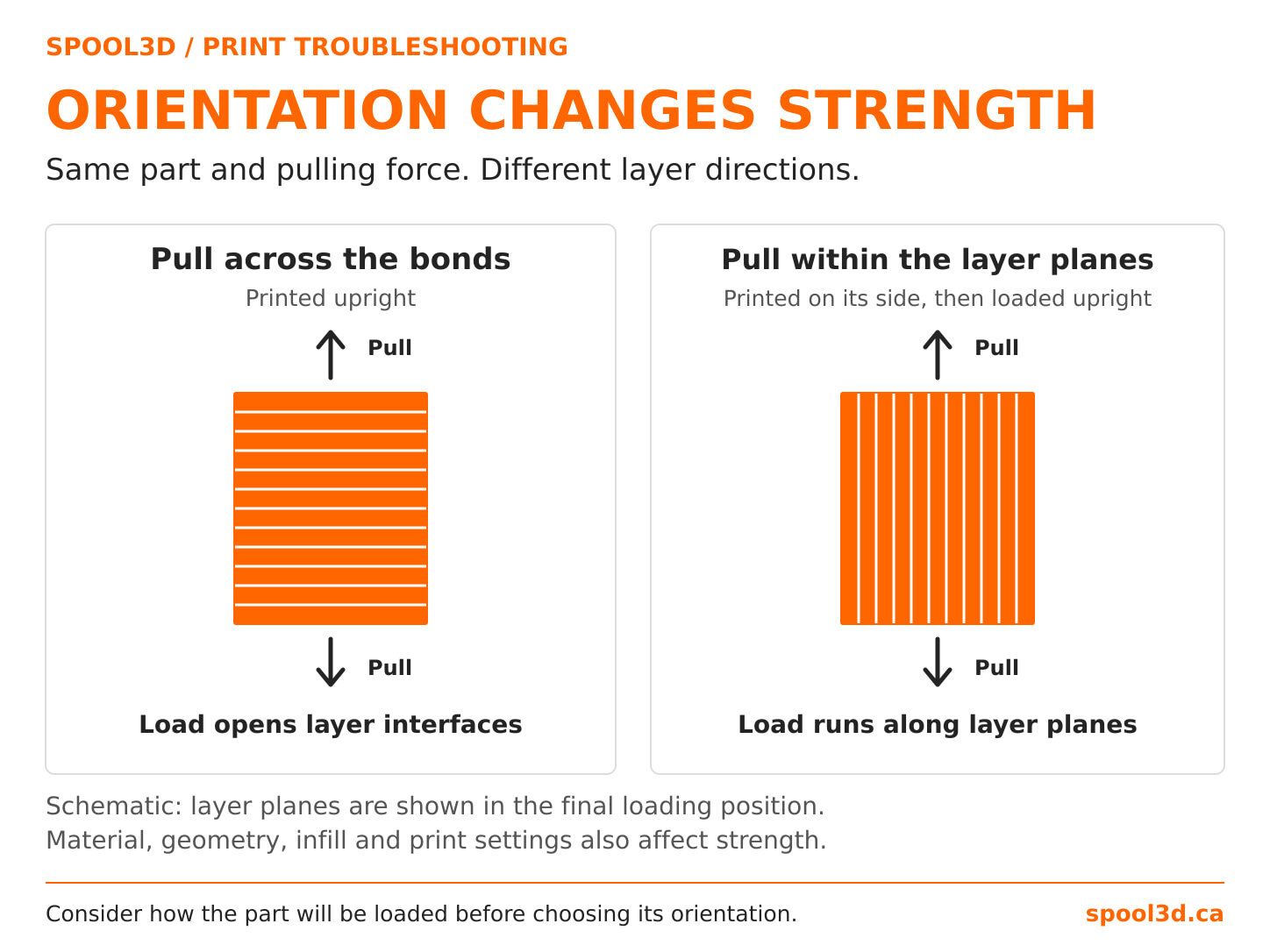
Even a well-printed part does not behave exactly like a solid block of the same plastic. Its strength depends partly on the direction of the printed layers.
A load that pulls neighbouring layers apart can expose a weakness that is much less obvious when the load runs within the layer planes. If a bracket or mounting tab repeatedly breaks along a layer line, inspect the print orientation before adding more infill.
Ask where the force enters the part. Does tightening a screw spread a thin wall? Does a long arm bend at a sharp corner? Could the part be rotated so that more of the main load is carried within the layers?
Wall thickness, rounded transitions and the shape around fasteners can matter too. Rotating a part may introduce new overhangs or support requirements, so compare the full result rather than treating one orientation as universally best.
8. Compare filament condition and material profiles
If the problem follows one spool, inspect the material as well as the printer. Moisture can affect extrusion and surface quality. Popping, bubbles and an unusually rough surface are useful clues, although none identifies moisture on its own.
Dry the filament using guidance for that exact material, and respect the spool's temperature limit. A dry storage box helps keep dry filament dry; it is not necessarily capable of drying a wet spool.
Then compare with a known-good spool of the same material using an appropriate profile. Keep the model, orientation and test method the same so the comparison tells you something useful.
Also check that a specialty blend is being printed with suitable settings. A profile chosen for another material or a different product line may be a poor starting point even when the spool looks similar.
9. Investigate failures that repeat at one height
If the break keeps occurring at the same height, inspect that area in the slicer preview. Look for a thin section, a major geometry change, a pause, or a change in temperature, cooling or speed.
Compare the model and toolpath with the failed part. A single weak band deserves a more targeted investigation than an entire print that is weak from bottom to top.
Record which layer failed and what the printer was doing at that point. That observation is more useful than making several unrelated setting changes and hoping one of them helps.
Run a comparison you can learn from
Choose a small, repeatable test that represents the failing feature. A large ABS enclosure may still need a taller or larger follow-up test because a tiny coupon will not reproduce its cooling conditions.
- Save the baseline profile. Record material, nozzle, orientation, temperature, cooling and maximum volumetric speed.
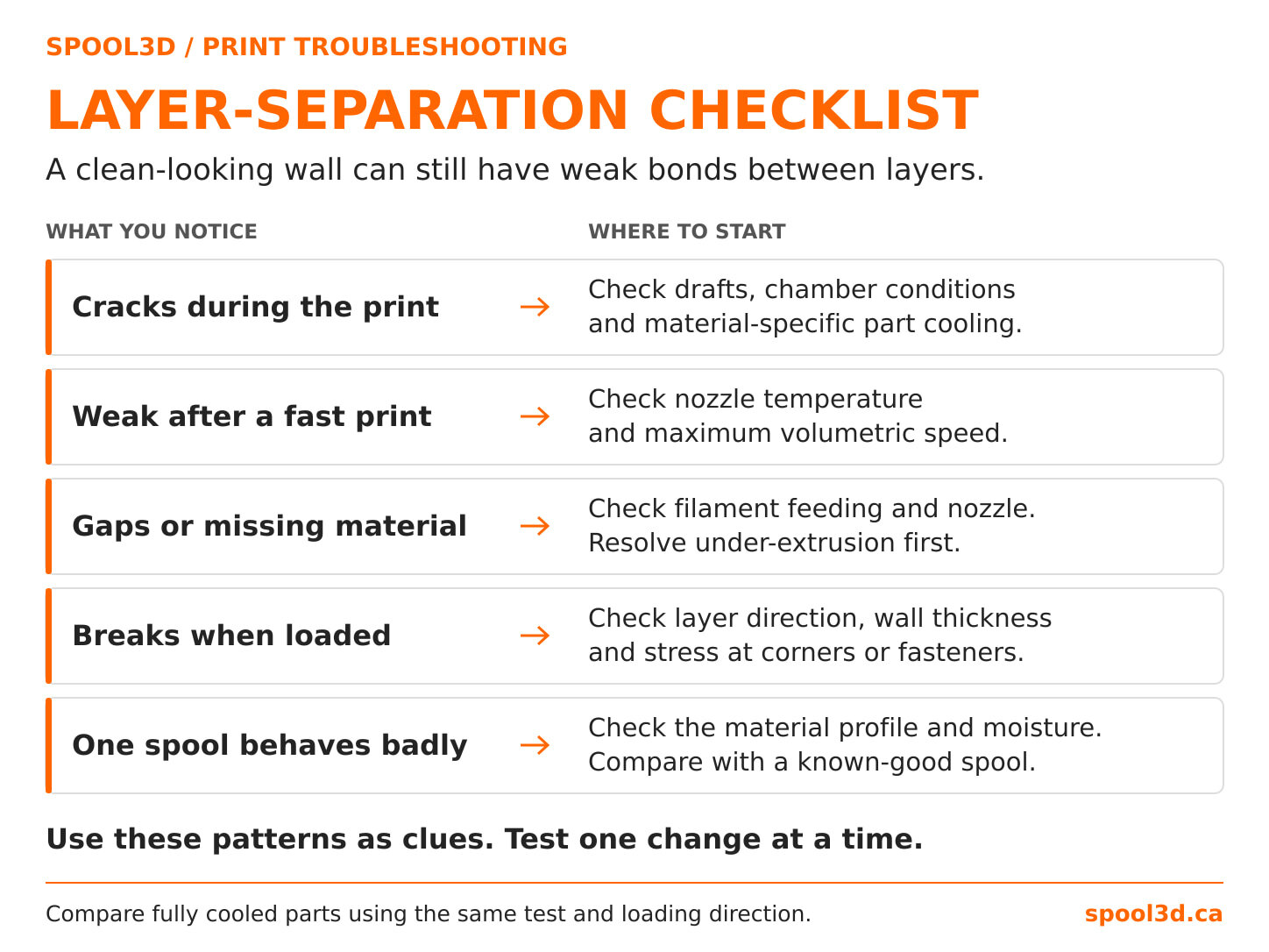
- Choose the first test from the symptom. Start with feeding faults if material is missing, flow demand if speed triggered the problem, or cooling and chamber conditions if cracks develop during printing.
- Change one variable. Keep the model and other settings unchanged.
- Let every sample cool fully. Compare using the same loading direction and method.
- Retest the actual part. Confirm that the improvement holds at its real size and geometry.
More infill cannot solve every weak print
Infill contributes to the way a part carries load, but it does not remove a bad bond between layers. Before increasing it, confirm that the printer is delivering consistent extrusion, the material is being processed appropriately, and the part is oriented sensibly for its job.
Spool3D carries replacement nozzles and PTFE tubing and fittings when a feeding fault needs repair. If the cause remains unclear, our 3D printer repair service in Calgary can help diagnose supported machines.
Technical references
- Prusa: layer separation and splitting
- Prusa: maximum volumetric speed
- Prusa: cooling settings and PETG printing guidance
- Prusa: ASA printing guidance
- Prusa: the hotend cooling fan
- Prusa: layers and perimeters
- Prusa: drying filament
- UltiMaker: material strength and part orientation
Use the material and maintenance guidance for your printer. The illustrations show typical symptoms and principles; they are not laboratory test results.
Recent Posts
-
3D Prints Splitting Between Layers? Causes & Fixes for Weak Layer Adhesion
A 3D print can have a smooth surface, tidy corners and a clean top layer, then split the first time …October 08, 2026 -
3D Printer Under-Extrusion: Causes, Fixes & Troubleshooting
Under-extrusion happens when your 3D printer deposits less plastic than the slicer expects. The res …October 06, 2026 -
3D Printer Layer Shifts: Belt Problem, Pulley Problem, Collision — or Something Else?
A layer shift can ruin an otherwise perfect print in a fraction of a second. The printer may run no …October 01, 2026