
Fix Rough 3D Print Top Layers & Pillowing | Spool3D
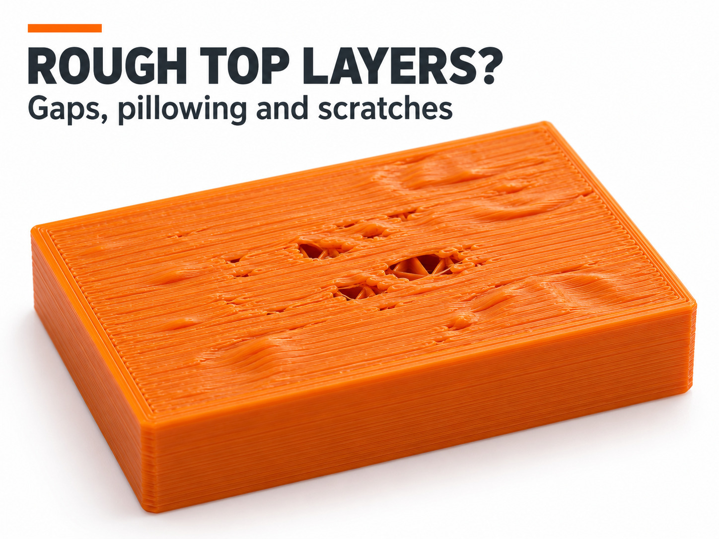
The walls look good. The corners are clean. Then the printer reaches the top of the part and leaves holes, raised ridges or a rough patch right where everyone will see it.
It is tempting to add more infill, increase flow or turn on ironing. Any of those changes might help a particular defect, but they solve different problems. A thin roof over sparse infill needs a different approach from a solid surface being scraped by the nozzle.
Start by looking at what the top actually shows, then check the layers beneath it in the slicer preview.
1. Identify the defect before changing the profile
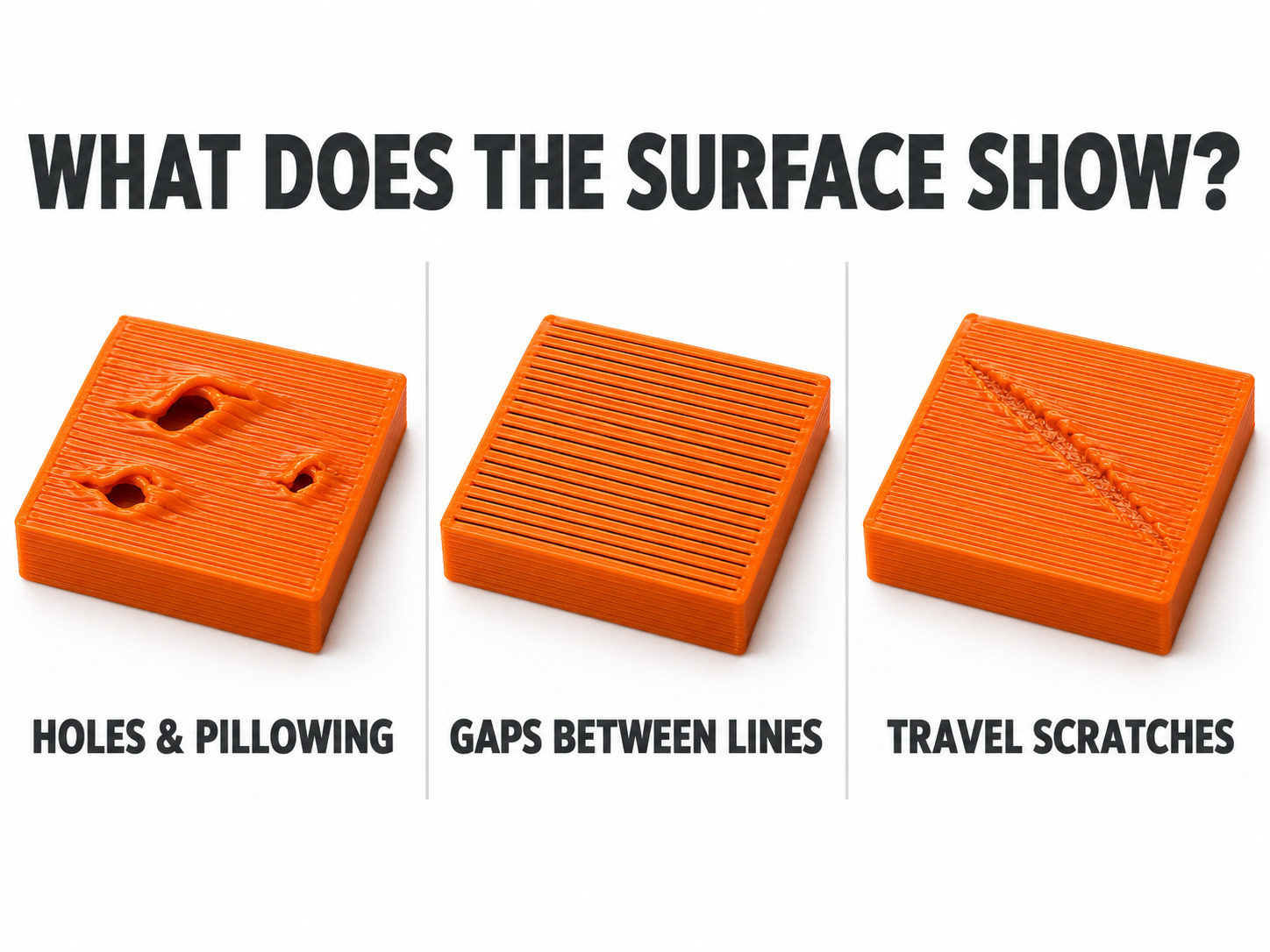
Pillowing describes an uneven top surface with raised or curled areas, sometimes with holes over the infill. It is different from a uniform pattern of small gaps between extrusion lines.
| What you see | Check first |
|---|---|
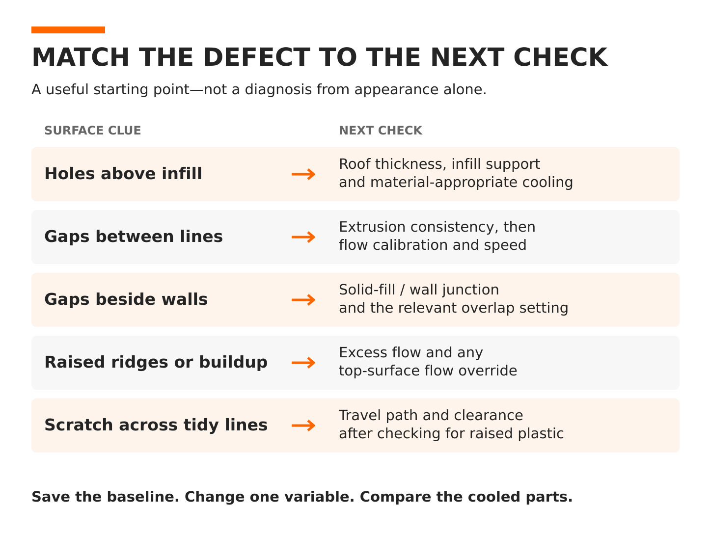
| Holes or raised patches over infill | Top-shell thickness, support beneath the roof and cooling |
| Gaps between most top lines | Extrusion consistency and flow calibration |
| Gaps mainly beside the walls | Where the solid fill meets the perimeters |
| Raised ridges or material piled up at edges | Excess extrusion and surface toolpaths |
| A scratch crossing otherwise tidy lines | Nozzle clearance during travel |
These are starting points, not definitive diagnoses. Compare the same area in the model and sliced toolpath so a designed opening is not mistaken for missing material.
2. Check top-shell thickness, not just the layer count
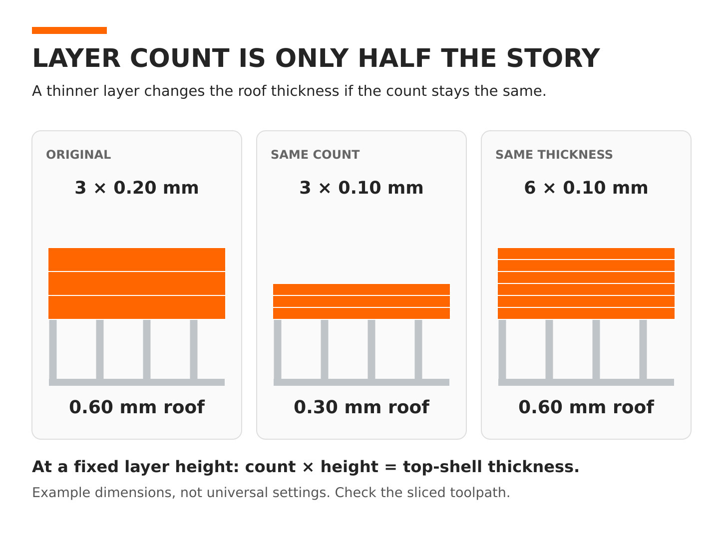
The first solid layer above sparse infill has to bridge the spaces between the infill lines. It may sag before later layers build a more even surface. If the roof is too thin, the printer can reach the final layer before those defects are covered.
Changing layer height changes the thickness produced by a fixed number of layers. For example, three layers at 0.20 mm total 0.60 mm. Three layers at 0.10 mm total only 0.30 mm. Six of those thinner layers restore the original 0.60 mm thickness.
Those numbers illustrate the relationship; they are not a recipe for every material or model. Review both the top-layer count and minimum shell thickness where your slicer provides them. With variable layer heights, check the actual sliced layers.
For a controlled test, increase the roof thickness while keeping infill and the rest of the profile unchanged. More top layers fill space inside the model; they do not make the finished part taller.
3. Look underneath the top surface
Scroll down in the preview to the transition from sparse infill to solid fill. Look at the distance that the first roof lines must span and whether they cross the supporting infill.
A modest increase in infill can shorten unsupported spans. Pattern and direction matter too: the same percentage does not give every pattern the same support at every height. Check the toolpath rather than assuming a favourite infill pattern will always solve it.
Also watch the real infill during printing. Thin, broken or poorly formed internal lines provide a poor foundation even when the preview looks correct. Repair that extrusion problem before adding a thicker roof.
For a large decorative model, a local infill modifier may provide extra support near the top without filling the entire part more densely. Inspect the result after slicing; the modifier needs to support the affected area.
4. Check cooling where the roof starts
Fresh extrusion needs to hold its shape across those internal gaps. Inspect the part-cooling fan and duct for blockage or damage, and check the cooling settings applied to the first solid layers above infill. Bridge overrides may differ from ordinary top-surface cooling.
Use the material profile as the starting point. PLA often benefits from substantial part cooling, while applying the same fan settings to ABS or ASA can introduce warping or weak bonds. Avoid treating maximum fan speed as a universal fix.
If the problem is confined to small areas, review minimum layer time as well. Do not change cooling and temperature together during the first comparison. If improved surface shape comes with layers that split, revisit our weak layer adhesion guide.
5. Separate missing extrusion from excess material
Uniform gaps between neighbouring lines can point to insufficient extrusion. Raised ridges, edge buildup and a nozzle pushing through surplus plastic can point the other way.
Confirm the nozzle and filament profiles first. If feeding is unreliable, the spool drags or the extruder clicks, use our under-extrusion troubleshooting guide before changing the flow ratio.
Once extrusion is consistent, follow your printer or slicer's flow-calibration procedure. Compare small adjustments using the same flat test surface. A flow ratio that is too low can leave gaps; one that is too high can create ridges. Increasing it until every hole disappears may simply exchange one defect for another.
If ordinary walls look good but the top does not, check whether a separate top-surface flow setting has been changed. Return unusual overrides to the known-good profile before stacking more adjustments on top.
6. Compare top-surface speed and extrusion demand
A fast profile can ask the hotend to melt more material than it can reliably deliver. Wider lines and taller layers increase that demand at the same movement speed.
Reduce top-surface speed for one comparison, and inspect internal solid-fill speed separately. A slow final pass may still sit on poorly printed layers below it.
If the lower-demand test improves, review the filament's maximum volumetric speed and temperature recommendations. That result does not prove the hotend is healthy: a restriction or feeding problem can also reduce its usable capacity. Keep temperature within the filament and printer limits.
7. Treat edge gaps as a separate clue
If the centre is filled neatly but a gap follows the inside edge of the walls, inspect the junction between the solid fill and the perimeters.
Slicers provide overlap settings to help those paths join. Names and calculations vary, so check the setting description for your slicer and confirm that it applies to solid top fill. Do not copy an overlap percentage blindly from another program.
Pressure advance is another setting that can sometimes default to an incorrect value.
After confirming reliable extrusion, test a small overlap adjustment or a lower relevant print speed, one at a time. Too much added material at that junction can leave a raised border. Recheck the whole surface, not just the original gap.
8. Follow scratches back to the travel moves
A diagonal mark across otherwise regular top lines can come from the nozzle travelling over the finished surface. Turn on travel moves in the preview and compare their direction with the scratch.
First check for surplus plastic or a raised area that brings the surface into the nozzle's path. Adding clearance does not correct over-extrusion or a curled print.
If extrusion is correct, a suitable Z-hop or travel-routing adjustment may prevent contact. Check when your slicer applies the lift; it may depend on retraction settings. Test the smallest useful change and compare print time and stringing as well as the scratch.
Repeated contact during extrusion, rather than travel, deserves a closer inspection of the print and printer. It is not simply a travel-lift setting.
9. Check filament condition when the roughness follows a spool
Pitting, bubbles and irregular texture can be associated with moisture-affected filament. They are clues rather than proof, particularly if temperature or the material profile also changed.
Compare with a known-good spool of the same material. If drying is appropriate, use the filament manufacturer's temperature and time guidance, and respect the spool's temperature limit. Store the dried filament appropriately afterwards.
A humidity reading inside a storage box measures the air around the spool. It does not directly measure water already absorbed by the filament. Avoid using that reading alone to rule moisture in or out.
10. Use ironing after the surface is consistently closed
Ironing makes an additional pass over a flat top surface, usually with a small amount of extrusion. It can improve the finish of a lid, nameplate or other horizontal face.
Get a continuous, reasonably even top first. Ironing is a finishing step, not a reliable repair for an unsupported roof or intermittent extrusion. Leave it off while diagnosing the underlying defect.
When you test it, use a small area and tune ironing flow, spacing or speed individually. It adds print time and can push material toward edges if the settings are unsuitable. Broad, slow ironing passes can also aggravate heat creep on susceptible setups.
If the surface is already solid but has inconsistent shine, try a monotonic top-fill pattern where available. Its ordered toolpaths can make the finish more uniform. It will not replace missing plastic or repair a collapsing roof.
A useful test sequence
- Save the baseline. Keep the original profile and photograph the defect.
- Inspect the preview. Confirm the affected face, roof thickness, underlying infill and relevant travel moves.
- Choose one test. Match it to the symptom instead of changing infill, flow and cooling together.
- Keep the comparison fair. Use the same model, orientation and filament, unless the spool itself is the variable being tested.
- Inspect the cooled sample. Check the centre, edges and side walls under the same light.
- Verify the full part. A small coupon may not reproduce the spans or cooling conditions of a large lid.
Fix the cause before polishing the finish
A clean top surface starts with a sound foundation, suitable cooling and consistent extrusion. Once those are working, surface patterns and ironing become useful finishing choices.
If inspection identifies a damaged component, Spool3D carries replacement nozzles and 3D printer cooling fans. For persistent faults, our 3D printer repair service in Calgary can help diagnose supported machines.
Technical references
- Prusa: layers and perimeters
- Simplify3D: gaps in top layers
- Prusa: cooling
- Prusa: extrusion multiplier calibration
- Prusa: maximum volumetric speed
- Simplify3D: gaps between infill and outline
- Simplify3D: scars on the top surface
- Prusa: drying filament
- Prusa: ironing
- Prusa: infill patterns
- OrcaSlicer: surface flow ratio
Follow the guidance for your printer and filament. Images illustrate typical symptoms and principles; they are not photographs of controlled test results.
Recent Posts
-
Fix Rough 3D Print Top Layers & Pillowing | Spool3D
The walls look good. The corners are clean. Then the printer reaches the top of the part and leave …October 14, 2026 -
3D Prints Splitting Between Layers? Causes & Fixes for Weak Layer Adhesion
A 3D print can have a smooth surface, tidy corners and a clean top layer, then split the first time …October 08, 2026 -
3D Printer Under-Extrusion: Causes, Fixes & Troubleshooting
Under-extrusion happens when your 3D printer deposits less plastic than the slicer expects. The res …October 06, 2026